BU406 Description
The BU406 is a versatile NPN power transistor with a maximum collector current rating of 4A and a collector-emitter voltage rating of 60V, suitable for handling medium power levels. The BU406 has excellent thermal performance and is easy to install.
BU406 Working Principle
The BU406 uses the principle of current amplification to control larger currents in electronic circuits. When a small base current is applied between the base and emitter terminals, it allows a proportionally larger current to flow from the collector to the emitter.
In a typical configuration, the transistor is used in either common emitter or common collector mode,. In common emitter mode, for instance, a small change in the base current results in a significant change in the collector current, allowing the transistor to function as an effective switch or amplifier.
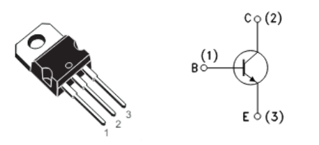
BU406 Pinout

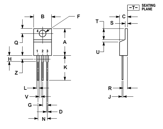
BU406 CAD Models

BU406 Marketing Diagram

BU406 Specifications
| Specification | Value |
| Type | NPN Transistor |
| Current - Collector (Ic) (Max) | 7A |
| Voltage - Collector Emitter Breakdown | 200 V |
| Vce Saturation (Max) @ Ib, Ic | 1V @ 500mA, 5A |
| Current - Collector Cutoff (Max) | 5 mA |
| DC Current Gain (hFE) | 40 - 150 |
| Power - Max | 60 W |
| Power Dissipation (Ptot) | 1 W |
| Frequency - Transition | 10MHz |
| Operating Temperature | 150°C (TJ) |
| Package Type | TO-220 |
| Mounting Type | Through Hole |
BU406 Features
- High Voltage
- Fast Switching Speed
- Low Saturation Voltage
- These Devices are Pb−Free and are RoHS Compliant
- NPN Transistor
- Very High Switching Speed
BU406 Applications
Switching Circuits: It is available for use in on/off control applications, such as relays and motor drivers.
Amplification: Utilized in audio and RF amplifiers, providing significant gain for weak signals.
Signal Processing: Employed in signal processing circuits for processing audio and video signals.
Power Supply Regulators: Functions in voltage regulation circuits to maintain stable output.
Power Amplifiers: Suitable for driving loads in audio amplification systems and similar high-current applications.
BU406 Package
The BU406 is housed in a TO-220 package, which features a sturdy metal tab for heat dissipation for efficient thermal management during operation. Additionally, the package includes three leads, which are designed for straightforward soldering onto circuit boards. TO-220 is suitable for a wide range of electronic applications, ensuring reliability and durability in demanding environments.


BU406 Manufacturer
The BU406 is manufactured by STMicroelectronics, a leading global semiconductor company known for its high-quality electronic components. With a strong reputation for reliability and performance, STMicroelectronics designs and produces a wide range of products, including power management solutions, analog devices, and microcontrollers.
How to Select and Use BU406?
When selecting a BU406, there are several factors to consider, such as voltage and current ratings. The BU406 has a maximum collector-emitter voltage of 800V and a continuous collector current of up to 4A. It is imperative that you observe the device's parameters to meet your circuit needs, including thermal management, switching frequency, and evaluate package types.
First, choose a suitable circuit topology, such as a switching power supply or a power amplifier. You also need to prepare a heat sink, input and output capacitors, and protection diodes. Then place the BU406 on the PCB according to the circuit diagram, paying attention to the correct connection of the pins. Then install a suitable heat sink for the BU406. Before turning on the power, check the circuit connections carefully.
After turning on the power, use a multimeter to measure the input and output voltages to confirm that the BU406 is working properly. You can also add protection measures to the circuit, such as a flywheel diode, to prevent reverse current from damaging the BU406.
BU406 Alternatives
| Alternative | Voltage Rating | Current Rating | Package Type | Features |
| BU407 | 40V | 3A | TO-220 | Similar voltage ratings |
| BU104P | 35V | 2A | TO-220 | Low power consumption |
| BU124 | 50V | 5A | TO-220 | High current capability |
| BU406D | 40V | 4A | TO-220 | Enhanced thermal performance |
| BU408 | 50V | 4A | TO-220 | Higher voltage rating |
FAQs
How do I test if a BU406 transistor is working?
You can test the transistor using a multimeter. Set the multimeter to the diode testing mode and check the base-emitter and base-collector junctions for proper forward and reverse bias characteristics.
Where can I find the datasheet for the BU406?
The datasheet can be found on the manufacturer's website or through electronic component distributors. It provides detailed information on electrical characteristics, thermal properties, package information, and more.